
Home
About Us
Clients
Photo Gallery
Contact Us


During the installation of process piping systems, it is critical for orbital welding personnel to work closely with Quality Assurance inspectors. The inspectors must be on site at the time of welding and inspect the welds as they are completed. Otherwise, the system would be welded together and it would not be possible to reach all of the welds with the fiberscope for inspection.
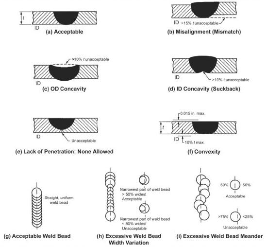 |
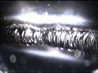
Figure 5. ASME BPE-2002 Figure MJ-1. Acceptance criteria for orbital tube welds. These visual weld criteria are intended to minimize the growth of microorganisms in biopharmaceutical tubing systems. Reprinted with permission from the ASME. |
Welds on product contact surfaces must meet the visual weld criteria of the Materials Joining part of ASME BPE-2000 Standards figure MJ- 1 shown in Figure 5. The ASME BPE visual criteria for orbital welds were developed to assure that welded joints do not provide a surface which would favor the growth of microorganisms that would contaminate the system. For example, an unpenetrated weld is a crevice where bacteria can grow and escape the cleaning process. ID concavity or misalignment of weld components could interfere with drainability and make cleaning problematic. Owners and contractors must decide prior to the job on an acceptance level for discoloration of orbital welds from the color chart shown in AWS Discoloration of the weld and heat-affected zone from oxidation resulting from poor purging during the weld sequence would reduce the corrosion resistance of the system. Any undetected weld failures that lead to system contamination.
When a certified welder begins work at the start of his shift he connects his orbital welding power supply to a dedicated circuit. He will determine the size of tubing and/or fittings or other components to be welded. The welder selects the appropriate weld head, installs the proper size tube clamp inserts (collets), and a tungsten electrode of Process Piping Installation the correct length. He then calibrates the weld head for rotational speed to the power supply. A certified argon source is used for the weld head purge which protects the outside (OD) of the weld as well as for purging the ID of the part to be welded.
Opening Coupon
before he can begin production welding, the welder must “coupon in” or performs a sample weld on the exact same material heat which is to be installed. Even with the restricted BPE sulfur range for 316L stainless steel, there is still some variability in weld penetration from heat-to-heat and schedules for different heats may vary by several amperes. A successful coupon demonstrates to the inspector that the machine is set up properly, the purge is adequate, and the welding operator knows how to operate the equipment.
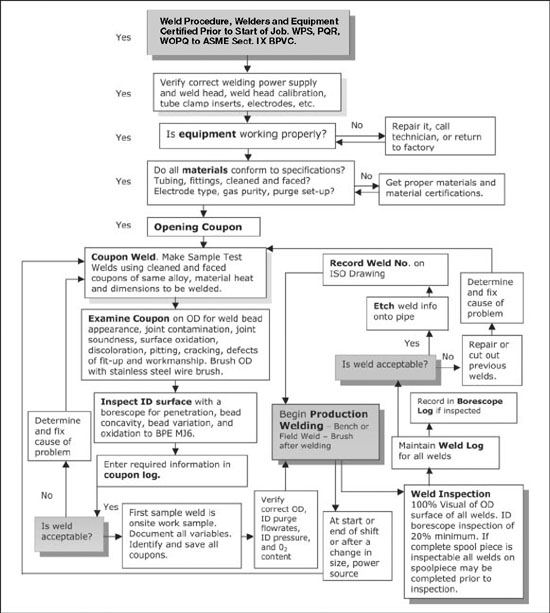
The first coupon of the day is referred to as the "opening coupon" and welders refer to this as "burning a coupon." Coupon welds must be done on an actual weld joint, not just a "bead on pipe" (which is a weld made directly on a tube without a joint) to assure that the equipment and the operator can properly align the components. When the weld is completed, the welder brushes the outside (OD) with a stainless steel brush to remove weld oxidation, removes any burrs or sharp edges from the ends of the coupon, and gives it to the inspector. A flow chart showing the sequence of welding, weld inspection, and weld documentation is shown in Figure 6.
|
Figure 6. Flow chart for orbital welding/inspection/documentation of stainless steel welds. |
Coupon Log
Every coupon, good or bad, must be recorded in a coupon log. The weld is identified by the machine used, in this case labelled A or B, with a sample weld number, for example SWA 001, the date, and the welder's ID number. The time of day, date, and material heat number, argon certification, orbital weld head, and power supply certifcate , and the entry is initialed by the inspector. All of this is cross-referenced to the installing contractor's weld procedure documentation. Test coupons are performed routinely if there is a change in power source, a loss of power, a change in purge set-up, or a change of welding operator. Test welds also are performed 100% of the time after a weld has been rejected before proceeding with production welding.
Bench Welding
Once the coupon has been approved, the welder prepares for production welding. He decides whether he will be doing bench welds or field welds and connects the ID purge to the system or components to be welded. Bench welding is done in a protected area where spool pieces up to
20 feet long can be prefabricated prior to installation in the field. Spool pieces can include up to three bends totaling 180° or two bends of 90° each to allow for baroscopic inspection. The BPE Standard requires 100% visual inspection of the outside of the weld and a minimum of 20% visual inspection of the inside or product contact side of the weld. The type of borescope used for weld inspection is flexible and more properly referred to as a fiberscope.
The installing contractor is responsible for knowing what length to cut tubing so that the finished spool piece will fit into the exact location in the field shown on the isometric (iso) drawing. The weld ends are cut and prepared in a square butt joint for welding. The components are held in a vise and a pipe stand to achieve the required slope of 0.6° according to the iso diagram. They are manually tack-welded together prior to welding. An ID purge must be used during tack-welding to prevent oxidation since an oxidized tack may prevent full joint penetration of the orbital weld. Unconsumed tack welds are a major source of weld rejection.
All of the welds in a spool piece may be performed before handing the assembly over to the inspector providing all of the welds are accessible to the fiberscope. Water-cooled weld heads used on this site permit high duty cycle welding and improved productivity. Welds were brushed on the OD prior to inspection,The ID purge remains connected to the spool piece until it is cool to the touch.
On a given spool piece, only one or two of the welds may be selected for inspection. On this job, 20% of the accessible welds had to be inspected, but in the process of getting the fiberscope to a particular weld, the QA inspector would see welds that were not scheduled for inspection. The weld inspectors estimated that they looked at about 90% of the welds although only 20% inspection was recorded. If the inspector saw a defect in a weld that was not listed for inspection, the defect would be reported and cut out. At that point, the inspection contractor would work with welding personnel to try to find the cause of the defect, eliminate the cause, and the welder would reweld the joint. All rewelded joints are borescope-inspected and the results indicated on the iso drawing as shown in Figure 7. In making rewelds, the welds must be kept far enough apart to avoid a second weld in the HAZ of the first since any detrimental changes to the metal from welding would be additive. A "pup piece" of the appropriate length may be used to keep the spool piece in conformance with the original dimensions.
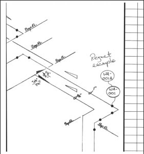 |
Figure 7. Example of how a rejected weld would be documented on an "iso" drawing. The first weld "window" shows the weld number which is recorded for every weld and the second window indicates that the first weld was cut out, replaced, and the number changed. Courtesy of Pro-Tech Process, Inc. |
Field Welding
much of the field or "position" welding involves welding together the spool pieces or connecting spool pieces to longer piping runs. Purging is critical for all welds, but particularly for field welds since purge gas of the required purity must be present at the weld joint to avoid oxidation, while the ID purge pressure must be adequate to deliver the gas to the joint without creating excessive pressurization. Excessive pressure on the liquid weld pool results in ID concavity or can even blow out the weld. The flowrate required to achieve the correct ID pressure varies in the field with the tube diameter with the distance from the source and with any restrictions upstream. It also changes if the system has branches. In that case, the flow rate was doubled from what it would have been without a branch in the system. One of the branches was capped off while the other had a restrictor on the exit orifice to help in achieving the correct ID pressure. An oxygen meter was used to monitor the ID purge gas to determine when it was safe to weld.
Field welds must be planned for inspection. Some of the field welds in the mezzanine were inspected with the fiberscope from the floor below. The slope was checked for every change of direction. For this job, the required slope was 0.6° or 1% which is approximately 1/8 inch per foot. The amount of slope varies with the job and the length of the piping run, but the system must be drainable.
Weld numbers are assigned by QA and are recorded in the weld log, on the iso drawing, and etched on the pipe. The weld log and information on the pipe contain the same type of information as was recorded on the coupon log. All of the bench and field welds were recorded in the weld log whether or not they had been inspected. Only inspected welds are recorded in the borescope log.
Weld quality cannot be inspected into the system, but is only as good as the welding equipment, weld procedures (SOPs), materials and surface finish, gas quality, cutting, cleaning, fit-up, and operator experience allow. Third-party QA assures that the welding equipment is functioning properly and that the installing contractor follows his own SOPs. A quality standard such as BPE-2002 fosters understanding between the owner, the installing contractor, and the inspection contractor as to the quality level to be expected in a finished system. Orbital welding has made it possible to achieve high quality welds on a repeatable basis resulting in more cleanable piping systems. This is essential for the successful production of biopharmaceutical products.
Orbital Welding of Skids
Orbital welding is used extensively in the manufacture of equipment skids such as CIP skids or skids with stills for producing WFI. A considerable amount of stainless steel tubing is used to connect the various components on the skids. The skids are assembled by orbital welding at the vendor and brought to the pharmaceutical plant for installation. All of these welds and the field welds done when installing the skid on site must meet the same welding QA requirements. Welds done during skid manufacture are inspected at the vendor.
Isometric Drawings put on CAD
At the end of the job, all of the iso drawings are entered on a computer. Using "plant North," the separate iso drawings can be "clicked" together to combine them in a single document which is then stored on CD as a permanent record.
Pressure Testing
After installation and before passivation, the piping systems are pressure tested. The pressure testing operation is overseen by the Inspection Contractor. This consists of filling the piping system with clean air, nitrogen, or argon at 150% of the design pressure or 150 psi, whichever is greater, and then monitoring the pressure decay for four hours. If there is zero drops in pressure, the system passes. This must be done with a calibrated gauge with certifications.