
Home
About Us
Clients
Photo Gallery
Contact Us


Introduction
Standards are important determinants of quality in fabrication. A decade ago, welding for pharmaceutical applications would have simply been qualified to ASME with reference to ASME B31.3. This assured the structural integrity of the weldments, but was not specific as to the quality of the weld surface on the inside of tubing which is essential for bioprocess applications. The 3A Sanitary Standards, first implemented by the Dairy industry in the US in the 1950s, offered guidelines for materials and fabrication techniques that mandated fully penetrated welds in sanitary piping systems, and attempted to set guidelines for workmanship and quality control in recognition that weld quality was a determining factor in the ability to maintain a piping system in a sanitary or hygienic condition. However, with the emerging biotechnology industry, it was felt that new standards were needed to meet the higher quality demands for the more complex, often delicate, and very costly bioengineered products. In particular, it was felt that there was a need for design criteria for equipment to enable it to be effectively cleaned and sterilized, and an emphasis on assuring weld surface quality once the requirement for strength was met. A need for standardized definitions also was recognized as well as the need to integrate existing standards for vessels, piping, appurtenances, and other equipment for the bioprocess industry without infringing on those other standards. In response to the special needs of the biopharmaceutical industry, the American Society of Mechanical Engineers (ASME) has developed a new standard to provide guidelines for the design and fabrication of facilities in which pharmaceutical products are manufactured by means of bioprocess technology.
The purpose of this discussion is to familiarize the reader with the concepts and intent of the BPE Standard, and the rationale for the use of orbital welding in the fabrication of bioprocess equipment and piping systems. It also is intended to guide those wishing to qualify orbital welding procedures to this Standard. It is not intended to be complete, nor to cover all parts of the Standard which pertain to welding, nor topics covered by the Standard but unrelated to welding, nor to be a substitute for the Standard which can be obtained from the ASME.1-4
The new ASME Bioprocessing Equipment Standard, ASME BPE-2009, was released in , but the process of writing this standard began much earlier when individuals at the 1989ASME Winter Annual Meeting determined that there was interest in the industry for such a standard, and approached the ASME Council on Codes and Standards to develop a standard for the design of equipment and components for use in the growing biopharmaceutical industry. The project was approved by the Council and a directive issued to the Board on Pressure Technology to initiate the project. The scope of the proposed standard included the design, materials of construction, inspection, testing of vessels, piping, and related accessories such as pumps, valves, and fittings for use in the biopharmaceutical industry. The ASME standard was not intended to replace existing standards, but wherever possible, the new ASME standard was expected to reference existing standards that are applicable to biopharmaceutical equipment design and fabrication. Throughout the writing of the standard, close relationships were established with other standards groups including the European CEN, ASTM, and 3A Dairy Standards.
The writing of the standard was accomplished by a Main Committee and several subcommittees which met several times each year until the standard was completed. These subcommittees were: General Requirements; Design Relating to Sterility and Cleanability of Equipment; Dimensions and Tolerances; Material Joining; Surface Finishes; and Seals.
Applicability
The BPE Standard applies to all parts of equipment and piping that contact either the product, raw materials, or product intermediates during process development, scale-up, or manufacturing and all equipment systems that are a critical part of product manufacture. This includes systems such as water-for-injection (WFI), clean steam, purified water, ultrafiltration, and intermediate product storage. Piping systems or parts of the system that do not contact the finished product are not covered by the BPE Standard. Pressure vessels, and steam-sterilized systems or any other systems which require pressure operation must conform to all applicable requirements of ASME B31.3, Process Piping. Qualification to the BPE Standard does not exempt users in any case where municipal, provincial or federal codes regulating pressure vessels and piping are in effect. The requirements of these codes must be met. Welding is used as a joining method throughout biopharmaceutical plants. It is used in the construction of pressure vessels and bioreactors as well as in the joining of piping systems. Orbital welding, which uses the Gas Tungsten Arc Welding (GTAW) process, is not used for pressure vessels or tanks as other welding processes are more suitable for this purpose. However, the GTAW process is frequently used for the product contact side of a vessel because of its high quality while faster methods are typically used for subsequent passes.
In this standard, tube and pipe are differentiated with tube referred to by its nominal OD, and pipe referred to by diameter and schedule. Orbital welding may be used to weld either tube or pipe. The dimensional tolerances of tubing makes it more suitable for autogenous orbital welding, but autogenous orbital welds of schedule pipe are practical for wall thicknesses of up to 0.154 inches (2 inch schedule 40). Orbital welding of pipe on applications requiring the addition of filler to the weld can be done using equipment with wire feed capabilities in sizes from 1/2 inch NPS and up. Orbital welding is commonly used to join tubing in piping systems for WFI, clean steam, and product lines. It also is used to connect tanks and vessels to the piping systems in the construction of equipment such as multi-effect stills as well as to connect bioprocess equipment mounted on skids. Typical tubing diameters for biopharmaceutical applications are 1 to 4 inches, but 1/2 inch OD instrumentation tubing (or smaller) may be orbitally welded and autogenous orbital welds with enclosed weld heads can be done on tube diameters up to 7 inches OD. Autogenous orbital welds of tube sizes up to 8 inches have been done for pharmaceutical installations using the more complex orbital welding equipment with filler wire capabilities which is generally used for larger diameter pipe. This type of equipment can be used for autogenous welds on pipe sizes up to 14 inch schedule 10. The decision on whether to use tube or pipe for a particular application would be based upon the pressure requirements of the system, surface finish requirements, availability of fittings with the proper end-preparation for orbital welding, etc.
Design Concepts for Cleanability and Sterilizability
A key feature of the BPE Standard is the concept of hygienic design where hygienic is defined as "of or pertaining to equipment and piping systems that by design, materials of construction, and operation provide for the maintenance of cleanliness so that products produced by these systems will not adversely affect human or animal health." In keeping with this concept, the Design Part of the Standard had as its objective to describe and outline accepted practices which have been shown to result in the fabrication of bioprocessing equipment that is both cleanable and sterilizable. It makes the distinction between preferred, recommended, and not recommended designations for particular designs and fabrication practices.
Bioprocess equipment is generally designed to be cleaned-in-place (CIP) rather than being disassembled for cleaning (cleaned-out-of-place or COP). The BPE Standard addresses only automated or manual CIP processes and automated steam-in-place (SIP) processes, but not hot water, 176°F (80°C) sanitizing, or other methods of sterilization. In order for CIP and SIP to be effective, the inner surfaces of piping and equipment must be smooth and free of crevices so that it is cleanable and resists to the extent possible the colonization by microorganisms. Equipment also must be designed and fabricated so that deadlegs are held to an absolute minimum where a deadleg in a piping system is defined as a pocket, tee, or extension from a primary piping run that exceeds a defined number of pipe diameters (L) from the ID of the primary pipe (D). For bioprocessing piping systems an L/D ratio of 2:1 is considered to be achievable for most valve and piping configurations. A deadleg is undesirable because it provides an area of entrapment which may not be reached by cleaning or sterilizing procedures and thus leads to contamination of the product. It has been shown that it takes more heat over a longer period of time to achieve sterilization in an air pocket than in spaces that are reached by steam since moist heat is much more effective in achieving sterilization than dry heat.12 Cleaning solutions used for CIP must be able to reach all parts of the system at sufficient velocity to ensure the removal of soil or deposits by chemical and/or mechanical cleaning, and all joints must be capable of being CIP cleaned and SIP sterilized.
Drainability is important for maintaining bioprocess systems in a clean and sterile condition. Fluid remaining after draining becomes a colonization site for bacteria or other microorganisms creating an unacceptable bioburden to the system. Sites where fluid accumulates also may become a corrosion-initiation site adding additional contaminants to the system. The design Part of the BPE Standard calls for holdup volume, or that amount of liquid which remains in the system after draining is complete, to be minimized by design. For a piping system to be drainable, lines must be sloped to no less than 3 inches per 50 ft (75 mm per 15 m) or 0.5% as a minimum with a recommendation for 1/4 inch per foot (20.8 mm per m) or approximately 2% for short runs and 1/8 to 1/16 inch per foot for field runs, skids, and transfer panels.
Connections to equipment shall use acceptable hygienic design connections as agreed to by the owner/user and the manufacturer (contractor) which means that threaded connections must not be used where they would come in contact with the process since the machined threads are likely to entrap soiled material and provide areas that cannot be reached by cleaning. Similarly, the number of bolts must be held to a minimum.
The optimum design for cleanability and sterilizability of bioprocess systems will have a minimal number of connections. For those connections that are required, buttwelded connections are to be used wherever possible since welded connections present the lowest risk of contamination. For welding of biopharmaceutical tubing in the US, the ends of the tubing are mechanically squared, butted together, and typically joined in an autogenous weld using automatic orbital tube welding equipment. An autogenous or fusion weld is one which is fused without the addition of filler metal. Welding is not limited to tube-to-tube welds, but is used to join tubes to fittings and is recommended for joining all hygienic valves into the process line.
When ferrules and ferrule connections are used, it is recommended that they be as short as possible to ensure that deadlegs are minimized. Any fittings used must be designed so that the interior is of a flush design or with a bulge concavity not exceeding 5% of the wall thickness so that a readily cleanable and drainable surface is exposed to the bioprocessing fluid.
Although welds are the most secure type of joining method, the surfaces of the weld bead on the inside of the tubing must be smooth and crevice-free in keeping with the concept of hygienic design. Any lack of fusion, porosity, or excessive buildup of material on the ID may provide a site which is inaccessible to cleaning or sterilization procedures. While hygienic systems can be achieved with manual welds, orbital welds are generally smoother and much more likely to provide a crevice-free surface on a repeatable basis.
Materials
For bioprocessing systems, the materials of construction for product contact surfaces must be fairly inert so as not to contaminate or otherwise affect the integrity of the product. The materials must be compatible with the bioprocessing environment including the temperatures reached during steam sterilization which are saturated steam at a minimum temperature of 266°F (130°C) for a duration of at least 100 hours under continuous steady state conditions. The materials also must be able to withstand high operating pressures and endure harsh chemical and mechanical cleaning procedures. The material recommended for use in bioprocessing systems is type 316 stainless steel (UNS 31603), or where it is to be welded, type 316L. Other higher alloy materials such as AL6XN or 2205 duplex may be used where higher corrosion resistance is needed, or other materials may be used as agreed upon by the purchaser and manufacturer. However, materials shall be identified by an industry recognized standard. Type 316 and 316L belong to the 300 series of stainless steels which are included in P number 8 according to the classification in ASME Section IX BPVC in which base metals with similar properties are grouped. The 300 series was selected by 3A for use in the dairy industry because it was cleanable and reasonably corrosion resistant, and that standard has been applied by the pharmaceutical industry. Although type 304 was the most commonly used alloy in the past, it has gradually been replaced by types 316 and 316L for hygienic applications because these alloys, although very similar to 304 in chemical composition, contain 2-3% molybdenum which significantly increases the corrosion resistance. Fluids used in bioprocess systems are frequently high in chloride concentration presenting a challenge to the corrosion resistance of stainless steel systems.
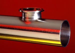
Figure 6. An orbital weld of a short sanitary ferrule to a pulled tee on 316L stainless steel tubing. The use of short welded ferrules is recommended to keep deadlegs to a minimum and this is easily accomplished with orbital welding technology. |
|
The choice of 300 series was fortuitous for welding since it is easily weldable and machinable. Compared to higher alloys, the loss of corrosion resistance by autogenous welding for 316L is minimal. Autogenous welding is less costly than welding with filler not only because the expense of filler is avoided, but also because orbital welding equipment for autogenous welding is less expensive than orbital welding equipment which has the capability of adding filler wire to the weld. Thus a material that can be autogenously welded is an economical choice. Furthermore, welding procedures are fairly simple since no preweld nor postweld heat treatments are required. These properties make 316 stainless steel a practical and cost effective choice for bioprocess systems.
The chemical composition of type 316 stainless steel is specified by ASTM 269, Seamless and Welded Austenitic Stainless Steel Tubing for General Service; ASTM A270, Specification for Seamless and Welded Austenitic Stainless Steel Sanitary Tubing and ASTM A 312/A 312M, Seamless and Welded Austenitic Stainless Steel Pipes. The L version of 316 has a lower carbon content which is 0.035 rather than 0.08% in standard 316. The low carbon version is preferred for welding because it reduces sensitization or carbide precipitation which may occur in the heat-affected-zone (HAZ) of welds during welding. In the temperature range of 800 to 1500°F, which occurs at some distance at either side of the weld, carbon comes out of solution in the austenite grains and migrates to the grain boundaries. Chromium migrates from the grain boundaries to combine with the carbon as chromium carbide leaving the grain margins depleted of chromium. Since the corrosion resistance of austenitic stainless steel depends upon a uniform distribution of chromium throughout the metal, depletion of chromium at the grain boundaries makes it susceptible to corrosion. The reduced carbon version of 316 does not completely suppress the formation of chromium carbide, but results in less loss of chromium during welding, and therefore, less loss of corrosion resistance.
WELD PUDDLE PROFILES |
|
|
|
Figure 7. Left: The element sulfur has a profound effect on the fluid dynamics of the weld pool. When sulfur is in the medium to high range of AISI 316 SS, heat from the arc is transferred downwards in the weld pool resulting in good penetration. When the sulfur content is below 0.008 heat is transferred towards the edges of the weld pool resulting in shallow penetration with a tendency towards OD concavity. |
|
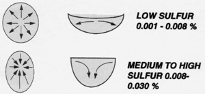
The element sulfur, which is present as a contaminant in stainless steel, has a significant effect on weldability as well as on the quality of surface finish that it is possible to achieve on any particular heat of base material. Although the sulfur content of AISI 316 and 316L stainless steel has a maximum of 0.030% sulfur, the BPE Standard has limited the sulfur content for weld fittings and tubing to between 0.005 and 0.017%. The reasons for this restriction are complex. Sulfur at higher concentrations promotes a tendency towards cracking and gives a rough appearance to the weld bead. Sulfur combines with manganese in the base metal to form manganese sulfide inclusions. During processing, these inclusions are rolled out and appear in scanning electron micrographs as "stringers." Corrosion tends to occur preferentially at the inclusion sites and when the inclusions are removed during electropolishing or passivation they leave a pitted surface.7 For this reason, tubing manufacturers which have to meet stringent surface finish requirements for the semiconductor and bioprocess industries prefer materials which are very low in sulfur. However, when the sulfur concentration gets into the very low levels, i.e., less than 0.005%, the material often becomes difficult to weld. The fluid dynamics of the weld pool changes when the temperature coefficient of surface tension goes from positive to negative at low sulfur concentrations.6 This has the effect of transferring heat in the weld pool outwards from the center of the weld so that when heat is applied the weld pool becomes wider before becoming deeper and the weld is shallow with a tendency to form a concave weld bead. With higher sulfur concentrations, heat is transferred in an inward direction resulting in deeper penetration with a narrower weld bead which is desirable. The higher sulfur concentration makes it easier to get a satisfactory weld.
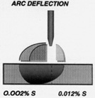
In compliance with the BPE Standard ASTM has added A270-95a Supplementary Requirements, S2 Pharmaceutical Quality Tubing 316, a supplement to ASTM A270 which limits the sulfur content to between 0.005 and 0.017%. This is a compromise which avoids the very lowest sulfur material which is difficult to weld, but restricts higher sulfur contents which are known to result in higher non-metallic inclusions and lower corrosion resistance. Users should be aware that welding of very low sulfur heats of material to heats in the intermediate to high levels of sulfur may result in deflection of the welding arc towards the low sulfur heat.9 This may result in a weld bead that fully penetrates the low sulfur side, but misses the weld joint. This problem is minimized by the sulfur requirements of the BPE Standard, but users should be aware of sulfur contents when welding unmatched heats together such as would be the case for the welding of tubes to fittings or to valves.
Surface Finish
The Surface Finish Part of the BPE Standard defines the criteria for the specification of interior surface finishes for vessels, distribution systems, and other components having contact with the product. Surface anomalies which would be detrimental to the process are defined and classified as a basis for acceptance or rejection of the material. Type 1 anomalies are those caused by an inherent property of the material such as non-metallic inclusions, while anomalies of Type 2 are caused by inadequate control of processing which would include scratches, grind marks, localized corrosion from inadequate removal of residuals, etc. Tables with acceptance criteria for the various anomalies are presented. Welds are classified according to whether the interior is to be ground smooth and flush on the ID with removal of visual pits and defects, ground smooth but not flush with the pits and defects in place, or as-welded with no grinding.
The smoothness of the surface finish is quantified by Ra measurements using a profilometer. For tubing Ra Average is used which is derived from readings taken at four cross sections approximately 90 degrees apart. The Ra, or roughness average is the log of the arithmetic mean of the surface profile. It is usually expressed in µ-inches (or µ-meters) where the Ra of As-Drawn and/or Mechanically polished tubing may be from 20 µ-inches (0.5 µ-meters) to 30 µ-inches depending upon the classification group with an Ra max of 30 - 45, µ-inches again depending on the classification. Tubing that has been mechanically polished followed by electropolishing will have an Ra of from 10 µ-inches up to 20 µ-inches depending on the classification with an Ra max of 15-30 µ-inches. Similar tables of readings for fittings and valves are presented.
It should be noted that welds on mechanically polished and electropolished tubing invariably have a rougher surface than that of the unwelded base metal. Although the smoothness of the ID weld surface is somewhat material dependent, orbital welds will in most cases be considerably smoother than manual welds on the same material.
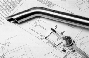
Dimensional Tolerances (DT) for Automatic Weld Fittings
The DT Part of the Standard includes tables showing acceptable dimensions for stainless steel hygienic clamp type fittings and 316L tube fittings to be joined by automatic welding. Fittings for automatic welding of pipe sizes are not included. The specifications for the dimensional tolerances for weld fittings to be used for orbital welding are important because the production of consistent high quality orbital welds depends upon consistent fit-up between tube and fitting in the orbital weld head. Good fit-up in turn demands consistently good end preparations of tubing and fitting as well as consistency of wall thickness and diameter.
Fitting tangent lengths for orbital welding were based upon dimensions of the weld heads of the various orbital welding equipment manufacturers. Ideally, the straight length of the fitting should be long enough to reach from the outside edge of the tube clamp inserts which hold the tube or fitting in the weld head to the center of the weld head where the tungsten electrode is typically positioned. With some orbital weld heads, it is possible to relocate the tungsten closer to the edge of the head to accommodate fittings with shorter stick-out.
Figure 8. An example of an orbital weld of a tube-to-an-elbow for use in a bioprocess application. |
|
The fitting ends must be square cut without burrs or breaks. Squareness is measured as a distance from a line drawn perpendicular to the tangent plane to the edge of the fitting which is 0.005 in (0.127 mm) for a 1/4 inch tube and .008 inches for a 2 inch tube, etc. If tube or fitting ends are not square, there will be a gap between the ends when they are positioned in the weld head, and the resulting weld may appear concave or, in severe cases, the arc may completely fail to fill the gap.
It is expected that the nominal wall thickness of the fitting be the same as that of the tube it is to be welded to. Welding current for orbital welding is based upon the wall thickness of the weld joint with approximately 75 amps of primary welding current and 25 amps of background current in the first level for a wall thickness of 0.065 inches. Inconsistent wall thicknesses will result in inconsistent welds. The wall thickness of fittings outside the control portion, such as the outside radius of an elbow, shall have at least 65% of the nominal wall thickness. The OD dimension is important since if the OD of the fitting is different from that of the tube, there will be a ridge on the ID of the weld that may interfere with drainability of the system.
When welding is used in the manufacture of fittings for this standard, the welds must meet the weld criteria of the Standard. Fittings, whether welded or not, must meet specified pressure ratings. Buttweld fittings made to this Standard would be 316L stainless steel unless otherwise agreed to by the owner/user and contractor. Weld fittings must be labeled with the heat number of materials used to make each part of the fitting. This is important to know in case of incompatibility between heats when welding tube to fitting. If the fitting is small, code numbers may be used for heat identification. The surface finish specifications for weld fittings must be in compliance with the surface finish part of the Standard, and fittings are to be protected by either sealed plastic bags or end caps and shrink wrap for shipping and handling.
Material Joining (MJ)
The MJ Part of the Standard applies to the joining of bioprocessing equipment which includes pressure vessels, tanks, and any vessels designed and built to the ASME Boiler and Pressure Vessel Code, Section VIII, Division 1; piping built to ASME B31.3; tubing and fittings, and is intended to be used in conjunction with these standards as they apply. The MJ Part, as with the other parts of the Standard, covers only those process systems which contact bioprocessing products or product-process streams. For the purpose of this discussion, only those systems which can be orbitally welded will be considered. Although joining methods other than welding are mentioned, at this point the MJ Part is concerned almost exclusively with the welding of 316L stainless steel. Where weld surfaces that contact the process are to be finished after welding, welding processes are limited to the arc or high energy beam (electron beam and laser beam) processes defined in ANSI/AWS A3.0. Where weld surfaces that contact the process are to be used as is, that is in the as-welded condition, welding processes are limited to the inert-gas arc processes (such as gas tungsten arc welding and plasma arc welding) or the high energy beam (electron beam and laser beam) processes. The Standard recommends that every effort be made to use an automatic or machine welding process such as an orbital tube welder. However, where size or space does not permit access with the weld head, manual welding may be used, but only by agreement between the owner/user and contractor. All welding processes are to be qualified to section MJ-8 of the BPE Standard.
Weld and finish samples are recommended before a job is begun to demonstrate that the desired quality can be obtained. The use of test coupons was recommended by the 3A standards in the 1950s and such test results demonstrated that the manual welder had the skill to make an acceptable weld. The use of test coupons is important for orbital welding because with orbital welding, it is possible to establish weld parameters to obtain an optimal quality weld on a particular heat of material that once established can be repeated with a high degree of accuracy from weld to weld indefinitely. Because of heat-to-heat variations in stainless steel, it is recommended that weld samples be done on the actual heat of material to be used on the job. For example, the degree of smoothness of the weld bead, the amount of weld bead penetration at a particular current setting, and even a tendency towards discoloration during welding is influenced by the quantities of trace elements in the base material.
Although the degree of repeatability is assured by the accuracy of the power supply, other factors which affect the weld also must be controlled in order to obtain weld consistency. These include consistency of tube and fitting end preparation, dimensional tolerances of tubing and fittings including valve stubs, cleanliness of materials, geometry and condition of tungsten electrodes, and workmanship standards. The standard provides for sample welds to be made on a regular basis as decided upon by the owner/user and contractor to demonstrate that the orbital welding equipment has been set up and is functioning properly, and that the purging procedures are effective. It is recommended that sample welds be made at the beginning of each work shift, whenever the purge source bottle is changed, and when the automatic or machine welding equipment is changed in some way such as by a change of weld head.
Acceptance criteria for welds on piping must be in accord with ASME B31.3 paragraphs 341.32 through 341.34 and Table 341.32A. For hygienic tubing and fittings, visual weld acceptance criteria including acceptance criteria for borescopic examination are detailed in the MJ Part of the Standard. Again the emphasis is on weld qualities which are consistent with the concept of hygienic design. Discontinuities such as cracks, voids, porosity, or joint misalignment that would promote contamination of the product are disallowed. Radiographic inspection is not a requirement of this Standard unless agreed upon by the owner/user and contractor or unless it is specified by another applicable code. Radiography is recommended for all joints which have been welded using consumable inserts to assure complete fusion.
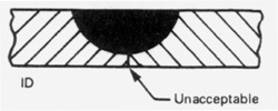
All butt welds must have full penetration of the weld bead to the ID. Lack of penetration where the weld bead is incompletely fused on the ID would create a crevice condition. The ID weld bead should be straight and uniform in width without indication of arc wander or erratic bead placement. The Standard specifies that for welds that cannot be inspected on the ID, that a minimum width of the OD weld bead must not be less than 50% of the widest part of the weld bead. However, if there is much variation in weld bead width on either the OD or the ID when using an orbital welding machine, this would indicate that the weld schedule needs further adjustment to assure uniform penetration of the complete weld joint from weld to weld. If pretacking is done, the tacks must be fully consumed by the weld. If the weld ID is not purged with inert gas during the tacking procedure, the welding arc may detour around the tacks resulting in a lack-of-penetration.
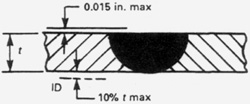
Alignment of tubing or other parts must be accurate so as to prevent a ridge that would lead to an unacceptable hold-up volume which would contribute to product contamination. This means that fittings and tubing must conform to dimensional tolerance standards and be installed by personnel trained in good workmanship practices. A maximum misalignment of 15% of the nominal wall is allowed.
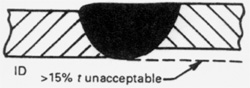
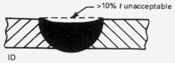
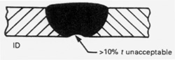
The weld bead profile of an autogenous weld should be flush on the ID and OD surfaces. Welds done with filler wire should be slightly convex, never concave, on the OD. Autogenous welds of pharmaceutical type tubing are usually flat on the OD unless excessive heat is applied in which case they will be concave on the OD with excessive penetration on the ID. The BPE Standard has a generous allowance for OD concavity allowing as much as 10% of the wall (0.0065" for an 0.065 wall tube) around the entire weld circumference or as much as 15% of the wall for up to 25% of the circumference. While orbital tube-to-tube welds are usually flush, it may be more difficult to do certain types of tube-to-fitting welds without some OD concavity. Excessive purge pressure on the ID will cause the weld bead to be convex on the OD and concave on the ID. Concavity on the ID of the weld bead is limited to 10% of the nominal wall. OD convexity is limited to 0.015 inches. OD and ID concavity combined must not reduce the wall thickness of the weld joint to less than the minimum specified design thickness for the tube or fitting.
Discoloration of the weld and HAZ may occur during welding as a result of oxidation. Oxidation, or heat tint as it is sometimes called, is known to cause a reduction in the corrosion resistance of stainless steel in proportion to the amount of oxygen contamination of the ID purge gas. The BPE Standard calls for the amount of discoloration of the ID surface to be minimized such that the weld bead is free of color, but with some light discoloration of the HAZ accepted provided that it is tight to the surface. The amount of discoloration to be allowed is subject to agreement between the owner/user and the contractor. It should be noted that color-free orbital welds are the norm for the semiconductor industry that routinely purifies purge gas to the low parts per billion levels of contaminants. The standard argon purge gas supplied for welding generally contains trace amounts of oxygen in the low parts per million range which should be no greater than 7 ppm, and also contains minimal amounts of moisture. In Europe, the standard for hygienic tubing discoloration is "light straw color" which occurs at about 20 ppm oxygen in the ID purge gas. It is possible to obtain color free welds on many lots of material with good purging techniques with standard argon purge gas with 1-2 ppm of oxygen and moisture. However, on some heats of material, particularly in the larger sizes, there is often a light blue "halo" or yellowish tint in the HAZ. It is more difficult to purge larger diameter tubing, and also more difficult to purge mechanically polished tubing than tubing that has been electropolished.10
The inert gas shield provided by an enclosed weld head offers more protection of the weld OD from oxidation during welding than an open frame type of head. It also protects the ID of the weld since the tubing ends may separate somewhat during the welding process allowing the exchange of gases between the ID and OD of the tube. If the tubing OD is open to atmosphere rather than to an inert gas environment provided by an enclosed head, there is a greater potential for contamination of the weld.
In the semiconductor industry and increasingly in biopharmaceutical installations, the use of gas purifiers and an oxygen analyzer to verify that the ID purge gas has not picked up contaminants before reaching the weld joint has become an accepted practice. Many mechanical contractors have experience in both the semiconductor and bioprocess industries, and are very familiar with high-purity purging techniques. This is an area that will need further attention in the future. The semiconductor industry is concerned enough with loss of corrosion resistance and contamination to experiment with heats of stainless steel with low manganese in order to prevent the precipitation of manganese on the HAZ which is associated with some of the discoloration. There is no clear standard in any industry for detecting color on welds since it may be visible in some lights but not other. One semiconductor manufacturer inspects their orbital welds with specified intensities of visible light and also with blacklight to detect discoloration. The biopharmaceutical industry has not yet reached this level of concern, and perhaps for many applications, it is unnecessary. However, it is important to understand that the technology is already in place for achieving a very high level of weld quality which will result in the optimal corrosion resistance for the material.
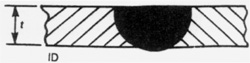 (a) Acceptable |
|
|
|
|
|
Figure 9. Acceptable and unacceptable weld profiles. |
Weld Inspectors and owner/users are to be allowed free access to work areas while work assigned to them is in progress as well as relevant certifications and documentation. An inspection plan, including the types of examinations to be made, shall be agreed upon in advance of the job by the owner/user and contractor. Inspectors who perform borescopic examinations are required at the owner/users' discretion to meet the requirements of ASME B31.3 paragraphs 340.4, 342.1 and 342.2, and may be certified as an AWS-QC1 Certified Welding Inspector. All welds are to be visually inspected on the OD and at least 20% of the welds selected on a random basis for each section are to be inspected on the ID either directly or with a borescope. Random inspections are important since welds of tube-to-fitting in which different heats are welded together are more likely to present a problem than tube-to-tube welds. Welding defects which may be repaired by rewelding include lack-of-penetration for which one additional pass is permitted and lack-of-fusion. However, it should be noted that each successive pass on a weld adds to the heat input and may result in a significant loss of corrosion resistance.
Other defects must be cut out or otherwise repaired at the owners' discretion. Experienced contractors have been able to reduce orbital weld reject rates to very low levels. One mechanical contractor was able to reduce the reject rate for orbital welds in bioprocess applications over a period of several years from 1.8 to 0.2%.
Weld Qualification to the ASME BPE-1997 Standard requires that the welds be certified to ASME Sect. IX of the BPVC, and meet the requirements of B31.3 Process Piping. For this, there must be a QA manual and a QA program in effect as well as a set of general weld standards which reference the BPE Standard. Qualified weld procedures must be developed, preferably on the actual heats of materials to be used. The orbital weld schedule which lists weld parameters such as welding currents, pulse times, rotational speed, and times is frequently used as part of the Procedure Qualification Record (PQR).
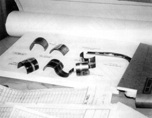
Figure 10. Weld qualification and quality control for orbital welding involves the use of sample welds known as test coupons made before the start of a job and at specified intervals during the job. Once acceptable procedures have been developed for orbital welding, consistent high-quality welds can be produced with a high degree of repeatability. |
|
Test coupons must be generated and subjected to destructive testing. Although existing standards have been used to qualify systems which have been installed by orbital welding, those standards were written with manual welding in mind, and this has lead to some confusion when qualifying autogenous orbital welds. Autogenous orbital welds are expected to be flush on the OD and ID, and do not require grinding in preparation for destructive testing. The tests include bend tests over a certain-sized radius in which two each of root and face bends are required to determine the ductility of the weldment. The test coupons must be carefully inspected after bending for cracks in the weld or HAZ. Tensile testing must be done to demonstrate that the base material still meets the minimum tensile strength (PSI) specified after welding. If the test specimen breaks in the weld, but still meets the PSI rating for the material, the weld is considered good. The limits of the weld range are determined by taking the minimum wall thickness qualified and then allowing up to two times the thickness with an unlimited diameter range. Radiography is not required by the BPE Standard unless it is required for another applicable standard.
When satisfactory test results have been obtained, the results must be recorded on the Weld Procedure Specification (WPS) Form QW-482, and the PQR Form QW-483, or equivalent forms. For welder certification, each welder must submit either 6 inches of linear weld (a 1.000 inch OD weld is 3.14 linear inches) for testing or multiple coupons, but no more than 4. Welder test results must be recorded on the Welder Performance Qualification form QW-484. Signatures of test personnel and a supervisor are required in confirmation of test results. Forms are available from the ASME. Each time a new welder is certified, he or she must repeat the above procedures for each and every weld which may be evaluated by either a bend test or X-ray.